Unit 5: Momentum
This unit, we learned about momentum. Momentum is a vector quantity with magnitude and direction, thus its equation is given by P=mv. In this unit, we learned about various types of collisions, the relationship between force, time and momentum (impulse), as well as the relationships between momentum and energy and momentum and kinematics.

Types Of Collisions
We looked at three types of collisions. In all three, momentum is always conserved. In perfectly inelastic collisions, the two objects stick together after the collision, and kinetic energy (K) is not conserved. In elastic, the two objects undergo no deformation after the collision and K is conserved. In inelastic, deformation occurs, and some K is lost.
Impulse
Impulse is equal to the change in momentum of any given system. In order for a system to experience a change in momentum, there must be an external force exerted on the system. Thus, change in momentum is equivalent to a force applied over a period of time. In equation format: J = Pfinal - Pinitial. Given that in most systems the mass stays consistent, we can utilize the momentum equation (P = mv) to rewrite impulse as J = m(change in v). Now, knowing that F = ma and (change in v) = (change in a) (change in t), we can derive our second formula for impulse: J = (average force ) (change in t). If you look at the graphic below, you'll see that an object's impulse can be represented by the area under a force-time graph.

LIL Charts (not to be mistaken with LOL)
Back in the olden energy unit era we were laughing every day as we drew LOL charts and contemplated the relationship between force, work, and energy. Now, in the momentum era, we have LIL charts and an opportunity to explore the relationship between force, impulse, and momentum. One of the primary differences between LOL and LIL charts other than the middle vowel in each is the fact that energy is a scalar quantity with no direction. Momentum, on the other hand, does have direction. If you refer to the LIL chart below you will see that the magnitude of the momentum of each object in the system has increased but no impulse has occurred. This is because the velocities are opposite, meaning that when combined into a system, the overall change in momentum is 0.

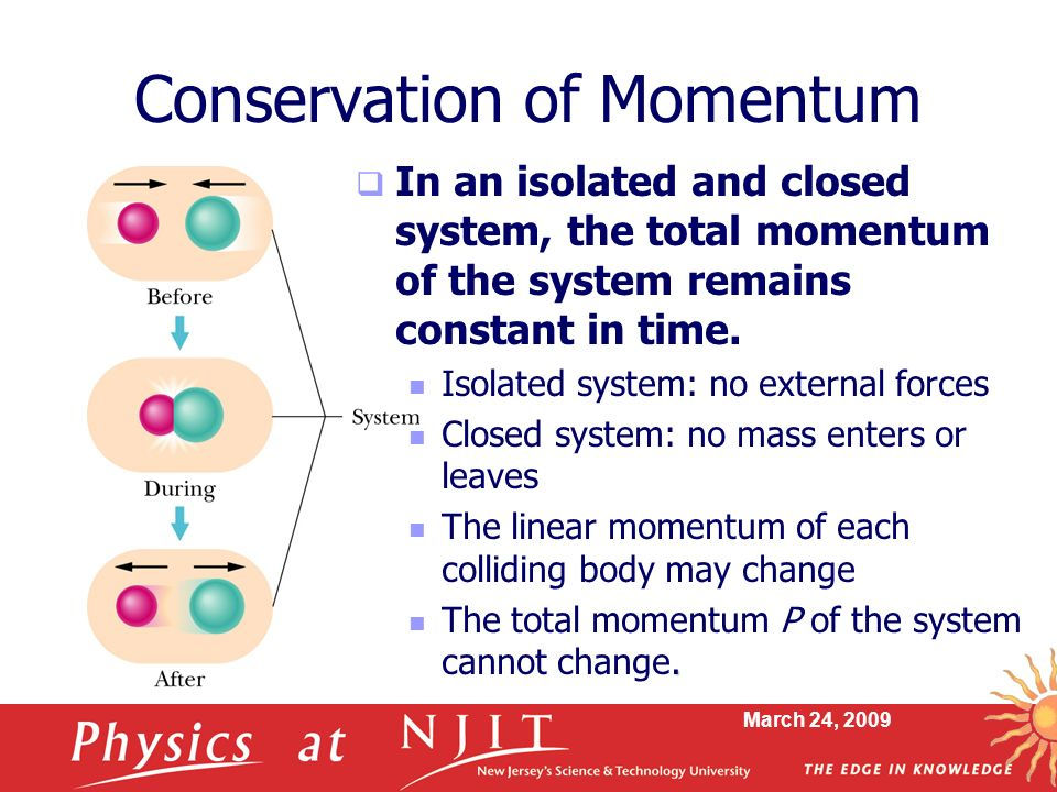
Conservation of Momentum
When thinking about conservation of momentum we must first consider the different between open and closed systems. In an open system, there are external forces acting on the system. For example, if the system is a baseball and bat, an external force could be applied by a person swinging the bat and hitting the ball into motion, increasing the system's momentum to a nonzero value. Before, both objects had velocity 0 and therefore no momentum.
In a closed system, we could define the system of the previous example as the bat, the ball, the earth, and the person. In this case, the person has initial momentum, which is then transferred to the bat and then to the ball. The gravitational force that acts upon the flying ball is considered to be within the system as well. Therefore, these four objects form a closed system.
Momentum is conserved within a system when there are no external forces. When there are external forces, there is impulse, and therefore a change in momentum.
The Fantastic Four: Momentum. Forces. Energy. Kinematics.
Helpful problems/explanations:
ENERGY/MOMENTUM
1) https://www.youtube.com/watch?v=sMGFB_pWCoQ
ENERGY/MOMENTUM
2) https://www.youtube.com/watch?v=9013Imlt0ZI
KINEMATICS/MOMENTUM
3) https://www.youtube.com/watch?v=5MLUbRqYQpk
Unit 4: Energy
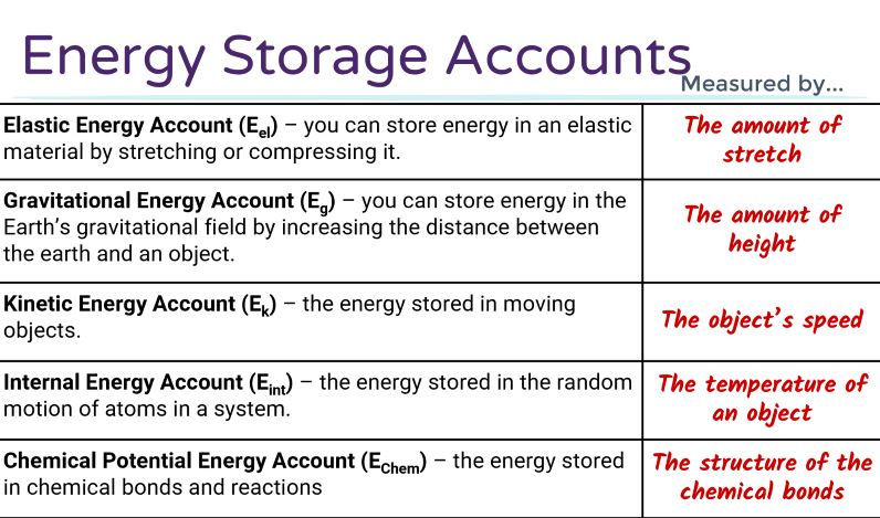
This unit was centered around energy, work, and power. Energy is defined as the stuff needed to do stuff, or in other words, change the universe. Work, then, is defined as the transferring of energy. One of the principal concepts of this unit was the conservation of energy, which states that energy is never created nor destroyed, thus the "loss" of energy is really just a transfer, where work has been done. The primary forms of energy we dealt with in this unit were kinetic, gravitational potential, and elastic potential. See graphic below.

LOL Charts
LOL charts are helpful tools that we can utilize to help depict the different energies involved in a system, the types of energies transferred, and the amount of energy transferred. LOL charts help demonstrate the conservation of energy within different situations. Below, I will include an example of a problem in which we may employ an LOL chart.

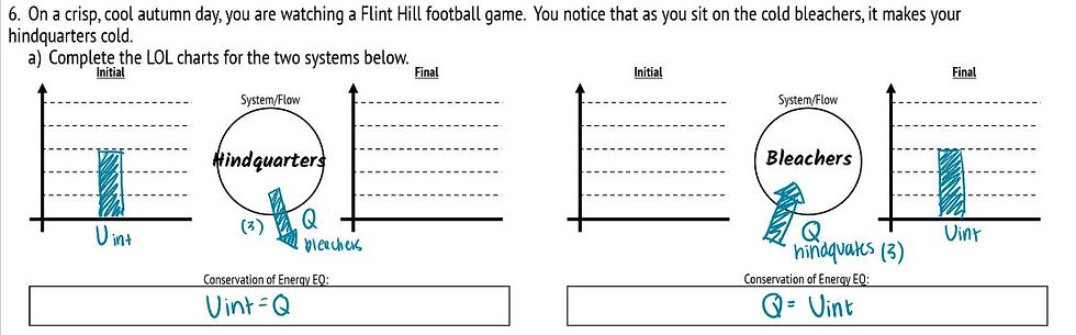
LOL Charts: The Hindquarters Dilemma.
In this problem, the form of energy we are dealing with is thermal energy, indicated by "Uint". The two LOL charts depict the energy transfers that occur for two different systems. The first system includes only the hindquarters, so we are only taking into consideration the energy within the hindquarters. In the initial state, the hindquarters contain 3 units of therm/internal energy. This energy is then transferred through work (Q) to the bleachers. However, since the first system does not include bleachers, we can say that energy was lost from this system. In the second system, the opposite occurs. The system only consists of the bleachers, therefore energy was transferred into the system via work. However, it is important to note that, as stated by the conservation of energy rule, this thermal energy was not created nor destroyed, but simply transferred. This is reflected in the conservation of energy equations, where the amount of work done is ultimately equal to the amount of energy that entered/exited the system.
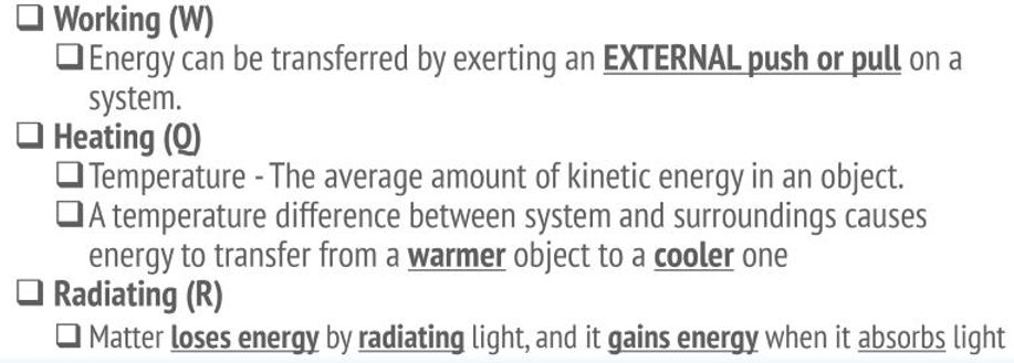
Other Types of Energy Transfer (Besides Work)
Energy Problem Solving
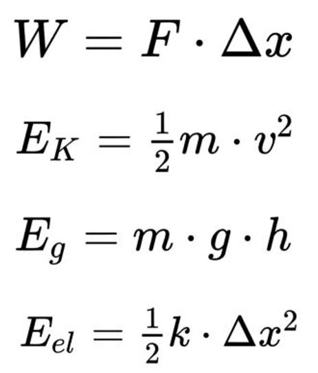
For many problems, the most effective method is to organize the given information first. This is when employing the aforementioned LOL charts and conservation of energy equations would come in handy. Another tool that is helpful is the energy equations for the different forms of energy. The graphic below displays these equations. In problems involving energy transfer, an understanding of how these equations can be manipulated to derive a value/variable is an essential skill. I will include an example below.
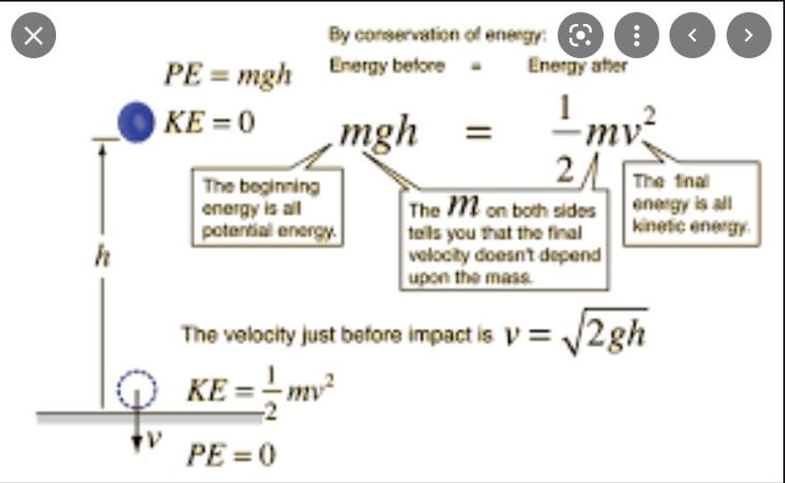
Gravitational Potential Energy -- Kinetic Energy
This set up above demonstrates the relationship between two different forms of energy in this particular problem: gravitational energy and kinetic energy. Knowing that the equation for gravitational potential energy is mgh, the equation for kinetic energy is .5mv^2, and that the conservation of energy equation applies, we can deduce that when the ball reaches its maximum height in the air, its velocity (v) will be 0 (.5m(0)^2 = 0), and thus the kinetic energy will be 0, and the ball will only consist of potential energy. When the ball is at the bottom, then, the height (h) of the ball will be 0 (m(9.8)(0) = 0), and thus the gravitational potential energy is 0 and so the ball has reached maximum kinetic energy.
Work
In the problem displayed above, there is no energy transferred in or out of the system (which consists of the ball and the earth). Therefore, there are no "work" calculations to be made. However, many energy problems will involve the transfer of energy, and therefore calculations regarding work. The graphic below offers the equations necessary for calculating the amount of work done.


Force * Change in Displacement
To offer a visual representation of calculating total work, I've included this graphic on the left. A force-displacement graph will have force (in N) on the vertical axis and displacement (in m) on the horizontal axis. The area under the graph represents the work done on the object. As you can see in the graphic, the different areas calculated over different intervals yields different amounts of work.
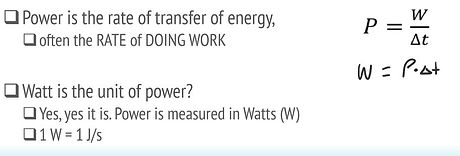
Power
Power is defined as the "rate of doing work", as you can see in the graphic on the left. The rate of doing work is given by P = W/(change in t), which can also be interpreted as the change in energy over time. Power is measured in watts, the standard unit being Joules/second.
Problem 1: Relating Energy to Forces
Concepts Targeted
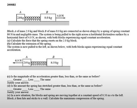
Part A of this problem calls on us to use concepts learned from the forces unit, employing force diagrams as well as knowledge about normal forces and spring forces.
Part B calls on us to then use the result from part A and solve an energy problem, finding the extension of the spring using knowledge of elastic potential energy, kinetic energy, LOL diagrams, and conservation of mechanical energy.
Parts C and D asks us to relate acceleration to energy.
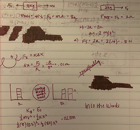
Solving the Problem
To the right is my work for parts A and B of this problem.
The answers I got for Parts C and D were the same and greater, respectively.
Problem 2: Potential Energy and Kinetic Energy
Concepts Targeted
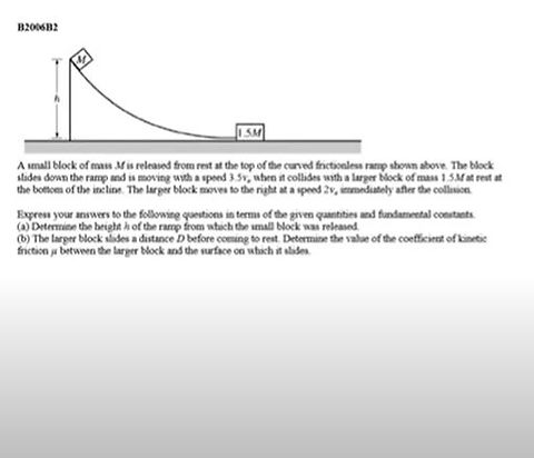
Part A of this problem asks you to calculate the height of the ramp. To solve this, you must equate Eg = mgh to K = .5 (M) (3.5v)^2.
Part B of problem asks you to determine the coefficient of friction. To do this, you must equate K = .5 (1.5M) (2v)^2 to Work = F (change in x).
Solving the Problem
My work for this problem is shown in the image on the right.

Problem 3: Connecting Kinematics (Velocity/Motion) with Energy
Concepts Explored
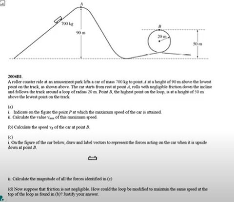
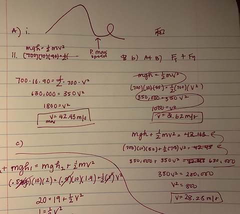
For Part A of this problem, we must determine the point P in which the car attains its maximum speed. Using our knowledge of mechanical conservation of energy, we would know that gravitational potential energy is at a minimum closest to the ground, so therefore kinetic energy will be at a maximum closest to the ground. For Part B, we were asked to calculate the speed of the roller coaster at B, the top of the small loop using concepts regarding gravitational potential energy, kinetic energy, and conservation of mechanical energy.
Solving the Problem
My work for this problem is in the image on the right.
Problem 4: Energy, Work, and Forces
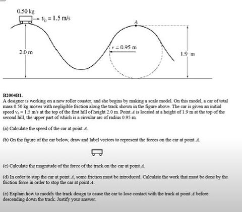
Concepts Explored
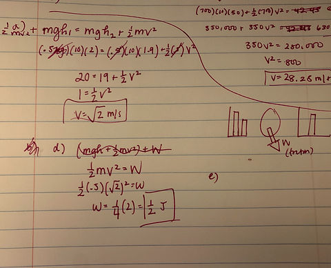
Part A of this problem asks us to calculate the speed of the car at A, employing concepts like conservation of mechanical energy, kinetic energy, and potential gravitational energy. Part D of this problem asks us to calculate the work done by the friction force to stop the car at A. Here, we can set work = kinetic energy, since the amount of work needed to bring the kinetic energy to 0 is the value we are looking for.
Solving the Problem
My work is shown on the right.
Unit 3 Content Page: Circular Motion
Unit 3 discussed two major concepts: circular motion and universal gravitation. In discussing circular motion, we determined it to be the motion of an object in a circle at a constant speed. As the object moves in a circle, it is constantly changing its direction; therefore it is constantly undergoing centripetal acceleration. At all instances, the object is moving tangent to the circle.
In discussing universal gravitation, we determined that every particle attracts every other particle in the universe with a force that is directly proportional to the product of their masses and inversely proportional to the square of the distance between their centers.
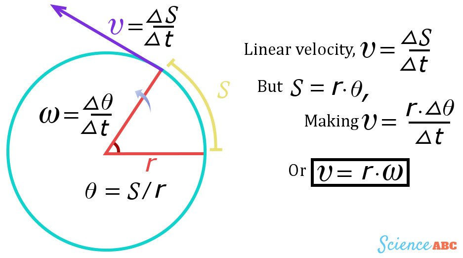
Angular Speed Tangential Speed
Multimedia Citation: https://www.scienceabc.com/nature/universe/what-is-tangential-velocity.html
To start off this unit, one of the most important concepts was angular speed and tangential speed. Angular speed measures the amount of time it takes for an object traveling in circular motion to complete revolutions. Thus, it is calculated by: (change in theta)/(change in time), as shown in the graphic above. Most often, we would convert revolutions/unit of time to radians/second, the proper unit for angular speed.
Ex. If a satellite completed 4 revolutions around Earth in one day, we would multiply 4 revolutions * 2 pi for the numerator and convert days - hours - minutes - seconds for the denominator to achieve the result:
Omega (angular speed) = 8 pi / 86400 seconds
In this unit, being able to convert back and forth between angular speed and tangential speed was another important concept. The tangential velocity of circular motion could be calculated using arc lengths (as shown in the graphic above) by determining the length of the arc traveled in a certain period of time. The formula for arc length is S = radius * angle of the arc. Thus, the conversion from angular to tangential speed could be calculated by multiplying the angular speed by the radius of the circle.
Ex. If the angular speed of a bob being spun on a string is 8 pi / 1 second and the radius of its rotation is 1 meter, the tangential speed would be calculated by multiplying 8 pi * 1 m, then dividing that by 1 second to get 8 m/s.
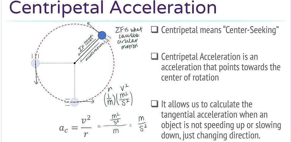
Centripetal Acceleration
In this unit, a specific type of acceleration was observed: centripetal acceleration. Centripetal means “center seeking”; in the graphic shown below, the acceleration of the blue object is center seeking in that it points towards the center of rotation. If one were to draw a force diagram to depict the motion of this object, there would be a force of gravity and a force of tension acting on the bob. In separating the horizontal and vertical components of this tension force, we are able to determine that the vertical component cancels out with gravity, leaving the net force as the horizontal component, which is consistently pulling the bob inwards, towards the center of its circular path.
Using vectors to visualize this, we see here to the left that the direction of the velocity vectors is consistently tangent to the path of motion, and the acceleration is consistently perpendicular to the velocity vectors. Thus, the acceleration the object experiences, which has now been determined to be the horizontal component of the tension force, pulls the object directly towards the center of its circular path, keeping the object in continual orbit.
Universal Gravitation
Multimedia link citation: https://sites.google.com/site/apphysics1online/circular-motion-gravitation/2-gravitation
Newton concluded that all objects attract one another with a "gravitational force". The magnitude of the gravitational force decreases as the centers of the masses increases in distance. In the graphic below, we see the equation that can be used to calculate the gravitational force between m1 and m2. "G" refers to the universal gravitation constant: 6.67 x 10^-11. "m1" and "m2" refer to the masses of the two objects, and "r" refers not to the radius of each object, but the distance between their centers of mass. Mathematically, the magnitude of the gravitational force decreases with the inverse of the square of the distance between the centers of the masses and in proportion to the product of the masses.

Combining the two concepts...

Multimedia link citation: https://slideplayer.com/slide/9782968/
Many of the problems we did in this unit involved a combination of concepts learned from centripetal acceleration and universal gravitation. One example of this would be determining the equation for the tangential velocity of an object in orbit using these concepts. In the graphic above, we can see that centripetal force was set equal to gravitational force (since the only force acting on an object in orbit is the gravitational force). Then, by eliminating and manipulating variables on both sides, we were left with the equation velocity = sqrt( G * (M/R) ).
UNIT 2 CONTENT PAGE: FORCES
Unit 2 was primarily on forces. In this unit, we studied Newton's three laws of motion using various experiments. We derived equations to represent the relationships between net force, mass, and acceleration. We learned about different types of forces and properties of forces. We spent specific focus on friction forces and spring forces. Using this knowledge, we then solved different force application problems. We learned how to utilize system schemas, free body diagrams, and force tables. We practiced using various equations and trigonometric equations to solve force problems.

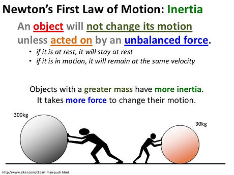
Newton's First Law: The Law of Inertia
Every object with matter has mass. Given that mass is a measure of inertia, and inertia is the tendency of an object to resist acceleration, an object’s “mass” is a measure of its ability to resist a change in its state of motion (in other words, resist acceleration).
An object with a small mass will exhibit less inertia and be more affected by other objects, and an object with a large mass will exhibit greater inertia and be less affected by other objects.
So in order for an object at rest to move or for an object in motion to change its velocity (speed and direction), there must be an unbalanced force exerted on the object. When all forces exerted on the object are balanced in equilibrium (Net Force = 0), the object will continue to be at a state of rest or continue to move at its current velocity, as described by Newton’s Law of Inertia.
Newton's Second Law: Fnet = ma
Newton’s second law is specific to the behavior of objects for which the net force is not zero, where there are unbalanced forces (that is, the object is accelerating).
Newton's second law of motion explains that the acceleration of an object is directly proportional to its net force and inversely proportional to the mass of the object. The following equations represent this relationship:
Fnet = m • a
a = Fnet / m
As the force acting upon an object is increased, the acceleration of the object is increased. As the mass of an object is increased, the acceleration of the object is decreased.
The above equation can also be used to explain the relationship between a unit of force, a unit of mass times, and a unit of acceleration. By substituting standard metric units for force, mass, and acceleration into Fnet = ma, the following is produced:
1 Newton = 1 kg • m/s2
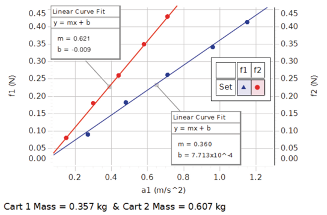
The graph above depicts a graphical representation of the net force and acceleration for two carts of different masses. In both cases, we can observe a linear relationship between net force and acceleration. It is also important to note that for the cart with a greater mass (.607 kg), a greater amount of net force is required for the cart to accelerate the same amount as the cart with a smaller mass (.357 kg).
Newton's Third Law: Force Pairs
A force is a push or a pull that acts upon an object as a result of its interaction with another object; thus, forces result from interactions.
Newton’s third law of motion explains that whenever one object exerts a force on another object, the second object exerts an equal and opposite force on the first object.
The term “equal” refers to magnitude; the size of the force on the first object equals the size of the force on the second object. The term “opposite” refers to direction; the direction of the force on the first object is opposite to the direction of the force on the second object. Forces always come in pairs that are equal in magnitude and opposite in direction.
Some forces result from contact interactions (normal, frictional, tensional, and applied forces) and other forces are the result of action-at-a-distance interactions (gravitational, electrical, and magnetic forces). According to Newton, whenever objects A and B interact with each other, they exert forces upon each other.
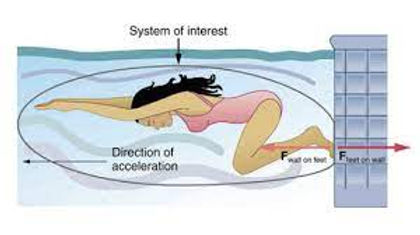
In the graphic below, the two objects interacting are the swimmer’s feet and the wall of the pool. The force exerted on the wall by the feet is a contact force; more specifically, an applied force. This force is equal in magnitude and opposite in direction to the force the wall is exerting on the swimmer’s feet, the force propelling the swimmer forward.
System Schemas / Free Body Diagrams / Force Tables
When solving a force problem, one should typically start with a system schema. System schemas can be used to identify all the forces acting on the object of interest, and all the objects and interactions involved. In this example below, the object of interest is the skateboard, and it can be determined that the skateboarder is exerting an applied force on the board, the Earth a gravitational force, and the ground both a normal force and frictional force.
The free-body diagram then identifies the direction and magnitude of all the forces depicted in the system schema. In this example, it is evident that the frictional force is much smaller in magnitude than the applied force; thus, we can infer that the board is accelerating in the direction of the applied force. The normal force and gravitational force appear equal, thus we can infer there is no vertical acceleration.
The force table then quantifies this information, which can then be used to solve force problems.


Force Calculations + Force Problems
Many force problems we encountered during this unit required understanding of Newton's Three Laws of Motion as well as knowledge of how to employ the formulas listed above.
One type of problem we encountered involved determining the forces acting on an object of interest having been given limited information about its mass and acceleration (see below). For these problems, a system schema, free body diagram, and force table would be utilized. Known information would be filled out, and from there, we could determine the best strategy for calculating the missing values.
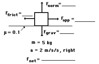
The formula Fw = mg, for example, was extremely relevant in this case. In this specific problem depicted below, the mass of the object is 5kg. Knowing this, we can calculate the Fgrav value (interchangeable with Fw) using Fw = (5 kg) * (-10 m/s^2). The acceleration of an object in free fall is -10 m/s^2. The Fgrav value is calculated to be -50 N.
From there, we can also determine the Fnorm value to be 50 N. Because the object is not at an angle, the Fnorm is perpendicular to the table surface, and thus we can determine that Fnorm = 50 N.
The formula Ff = (mew) FN is also useful in this problem. The problem states that the friction coefficient between the block and the table is .1 mew. Thus, given mew = .1 and FN = 50 N, we can determine that Ffrict = 5 N.
Now, the only remaining unknown force is Fapp. We can determine Fapp by first determining the net force applied on the block. The block is not accelerating in the y direction because Fgrav and Fnorm cancel each other out. Thus, the net force value calculated through Fnet = (5 kg)(2 m/s^2) tells us that the net force exerted on the object is 10 N to the right. Therefore, if Ffrict = 5 N to the left and the net force is 10 N to the right, we can conclude that Fapp = 15 N. Problem solved!
Representations of Motion and Force Models
Solving Problems with Forces and Motion
One of the connections between motion and force explored in this unit was vectors. In the previous unit, we utilized linear models and quadratic models to represent position, velocity, and acceleration. With the concepts learned in this unit, we can now use vectors to further break down the motion represented in these models. The graphic below represents the velocity of an object. This object is not traveling at a constant velocity, as evidenced by the quadratic model used to represent its velocity. Thus, we know that there is an unbalanced force exerted on the object; its net force is not zero. This graph includes vectors that break down the x component, y component, and angle of the net force at different points. These vectors provide a more specific representation of the speed and direction of the object's velocity.

Representations of Motion and Force Models
Solving Problems with Forces and Motion
Part 2
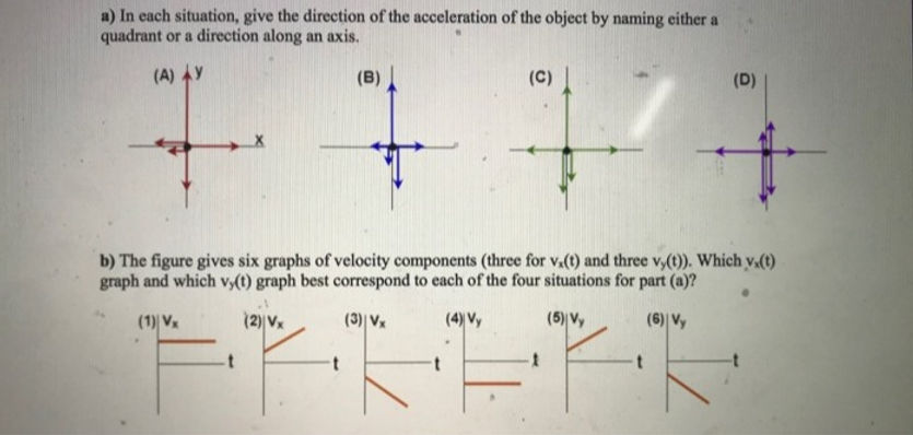
Another connection between motion and force explored in this unit was force diagrams. In the previous unit, we utilized linear models and quadratic models to represent position, velocity, and acceleration. With the concepts learned in this unit, we can now use force diagrams to represent different velocity components.
The graphic below offers four different force diagrams and six different velocity components (three horizontal ones and three vertical ones).
Here are the matchings:
A -- 1 (x), 5 (y)
B -- 2 (x), 4 (y)
C -- 2 (x), 6 (y)
D -- 3 (x), 6 (y)
In cases where the x components or y components opposite each other are equal in magnitude (for example, x component of force diagram A), the velocity is constant as well (a flat line) because the forces are balanced. In cases where the components opposite each other are not equal in magnitude, it would indicate unbalanced forces, and therefore the velocity would not be constant. Assigning North as the positive direction for the y component and East as the positive direction for the x component, we can then assign velocity graphs to force diagrams accordingly for the components with unbalanced forces.
UNIT 1 CONTENT PAGE

_edited.jpg)
Terminology
Position: location at a specific time, changes depending on time.
Distance: total units traveled, regardless of direction, always positive
Displacement: overall change in position, takes into account direction of travel, could be positive or negative
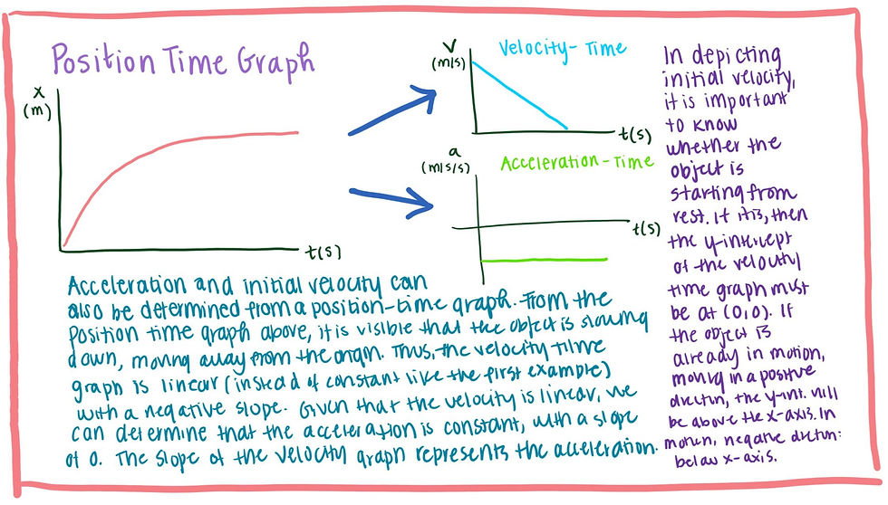
The graphic on the left offers a visual representation of the differences between position, distance, and displacement. The two points of position reference location at a specific time. At time t = 2, the object is at location = 2. At time t = 5, the object is at location t = 3. The total distance traveled differs from the displacement because the object did not travel in a straight line. The displacement is depicted as the shortest path from the start point to end point.
Strobe Diagrams
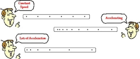
Strobe diagrams use dots to represent the position and time of an object each second.
From this example above, an object traveling at a constant speed is represented by dots that are all evenly spaced out.
In comparison, the object that is accelerating is depicted by dots that are increasingly further apart, meaning that for every second that passes, the object is covering more distance at a faster rate.
The third example, labeled "lots of acceleration" demonstrates an object accelerating at a faster pace; thus, the spaces between the dots grow larger faster.
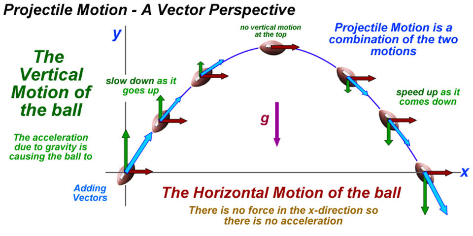
Projectile Motion
The definition of a projectile is any object which is projected into the air and continues to move due to its own mass. Projectiles have both horizontal and vertical motion, as depicted by the diagram below. The green arrows depict the vertical motion whereas the red arrows depict the horizontal motion.
The vertical motion of a projectile determines the amount of time it is in the air for, and the horizontal motion determines the distance that the projectile travels.
The horizontal velocity of a projectile is always constant because gravity has no affect on the speed of the projectile, thus there is no acceleration. The vertical velocity of a projectile decreases on its way up, hits zero at its maximum position, then increases on its way down.